

OEM Digital Vacuum Gauge Essentials for Reliable Pressure Measurement
2026-11-16
Pressure measurement shouldn’t be a guessing game. For technicians and engineers who rely on precision, a digital vacuum gauge is the difference between a smooth operation and a costly miscalculation. In this guide, we break down the essentials—from sensor accuracy to real-world durability—so you can make confident calls on the job. And if you’re looking for a gauge that holds up when it matters, HONGSEN has built a reputation for tools that don’t flinch under pressure.
Picking the Right Sensor Without Overpaying for Specs
Most sensor datasheets lead with resolution, range, and update rate, but those headline numbers rarely reflect what your device actually needs. A 16-bit accelerometer can look impressive while the extra bits drown in noise, and a sensor rated for 500 g is pointless when the real impact never exceeds 15 g. Start by listing the conditions the sensor will face, then pick specs from that list instead of from a comparison table.
A useful trick is to ask where the spec breaks, not where it peaks. If a temperature sensor claims ±0.1 °C accuracy, check the fine print for the temperature band, supply voltage, and long-term drift. The same goes for pressure sensors and gas sensors: a narrow sweet spot on a graph often hides mediocre performance across the range you actually use. Paying for factory calibration only pays off when your system cannot compensate in software.
Also separate raw capability from integration cost. A cheaper part with a noisy analog output may end up more expensive after filtering, shielding, and calibration labor. Conversely, a highly integrated digital sensor can be overkill if you already have a microcontroller that handles compensation. Match the sensor’s interface and footprint to your board and firmware, not just to a datasheet highlight.
How Often Should You Really Recalibrate?
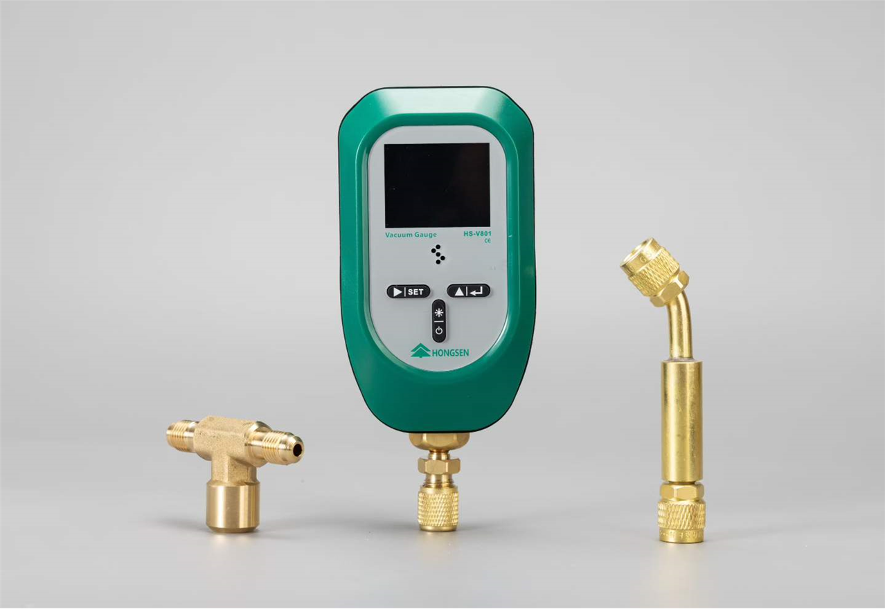
The answer depends less on the calendar and more on how the instrument actually behaves between checks. A pressure gauge in a clean, temperature-stable lab can hold its accuracy for months, while the same model bolted to a vibrating compressor skid may start drifting within weeks. Rather than defaulting to an annual cycle, look at the spread of your last few calibration records. If the as-found error is consistently tiny, you can stretch the interval a bit. If it's creeping toward the tolerance limit, tighten it.
Another signal worth watching is the consequence of a wrong reading. A device that only logs non-critical data can tolerate a longer gap, but one that triggers safety alarms or controls batch quality deserves a shorter leash. Many maintenance teams end up with a hybrid schedule: quarterly for high-risk loops, six months for general process instruments, and annual for bench tools that rarely move. That kind of tiered approach beats a blanket rule because it matches effort to actual risk.
If you're unsure where to start, pull the manufacturer's suggested interval and treat it as a ceiling, not a target. Then adjust based on your own history. It's normal to recalibrate more often early on, until you have enough data to justify extending the window. The goal isn't to hit a number on a spreadsheet; it's to catch drift before it costs you a bad batch or a false alarm.
Signal Outputs: Matching Your PLC Without Extra Hardware
Field devices rarely speak the same language as your PLC. One sensor pushes 24V high, another sinks current to ground, and a third pulses a train of millivolt signals from an encoder. Instead of stacking interposing relays, signal conditioners, or isolated converters in the panel, you can often match these outputs directly to the PLC input card by understanding what the card actually accepts. Many modern PLCs combine sink/source configurable inputs, high-speed counters, and even analog ranges on a single slice of I/O—so the missing link is usually configuration, not hardware.
Start by mapping the output type to the input channel's electrical signature. A PNP sensor output (sourcing) connects cleanly to a sinking input card, while an NPN output needs the opposite. If your PLC offers a shared common with switchable polarity, one wiring change flips the entire group. For frequency or pulse outputs, skip the standard DC input and assign the signal to an onboard high-speed counter—set the filter time to catch the fastest pulse without swallowing noise. Analog signals are trickier: a 0–10V output works with voltage inputs, but a 4–20mA loop may need a scaling resistor only if the input card lacks a dedicated current range. Read the card's spec sheet for input impedance and resolution before assuming compatibility.
The real art is using built-in diagnostics to verify the match without a scope or meter. Force the output from your device and watch the PLC's input LED and raw data register. A flickering value near the threshold often means the signal voltage is marginal, or the wiring is picking up induced noise. Adjust the input filter time, add a pull-up or pull-down resistor if the output is open-collector, or reverse the common polarity if the logic reads inverted. When the raw count matches expected physical units—whether it's a proximity switch, a flowmeter pulse, or a linear position—you've achieved a clean signal handoff with zero extra hardware.
Wetted Materials: Chemistry Compatibility Beyond the Datasheet
Datasheets give you a neat table of chemical resistance ratings, but real-world wetted materials face a messier reality. Temperature swings, fluid mixtures, and trace impurities can turn a supposedly compatible polymer into a swollen, brittle failure. Instead of trusting a single static list, experienced teams cross-check actual service conditions—like intermittent exposure or cleaning agents—against long-term field data and manufacturer test reports.
One overlooked variable is the difference between immersion and intermittent contact. A seal that handles a brief splash of solvent may degrade rapidly when continuously submerged at elevated temperature. Similarly, elastomers can absorb process fluids, changing their mechanical properties even if no visible attack occurs. Practical compatibility means testing coupons in the exact fluid blend, including any additives or degradation byproducts, rather than relying on generic chemical class ratings.
Unexpected incompatibilities often show up at system boundaries: gaskets, O-rings, diaphragms, and tubing liners. Swapping a pump head material without re-checking every wetted component invites premature failure. A more robust approach layers supplier data with in-house exposure logs and visual inspection after each maintenance cycle, building a living compatibility map that reflects how materials behave in your specific process—not just on a printed chart.
Mounting Pitfalls That Throw Off Vacuum Readings
A vacuum gauge can lie to you without ever being defective. The usual suspects aren't the electronics or the sensor itself but the way the gauge is bolted onto the system. A classic mistake is mounting the gauge too far from the chamber it's meant to measure. Long, narrow tubing between the process and the sensor creates a pressure drop, especially in low-pressure systems where gas flow is minimal. You'll see a reading that looks stable but sits nowhere near the actual chamber pressure. Short, wide ports are your friend here; anything else invites a false sense of security.
Another trap is ignoring the orientation and location of the connection. If the port points upward and collects condensable vapors or pump oil, those liquids can pool right at the sensor diaphragm. The gauge then measures the vapor pressure of the gunk rather than the system's gas pressure. Mounting the gauge sideways or downward, with a slight tilt away from the process, lets gravity keep the sensing element clean. Even better is adding a small isolation valve so you can close off the gauge during roughing or backfilling, then open it only when you need a true reading.
Thermal effects also sneak in through the mounting hardware. A gauge clamped to a hot chamber wall without any thermal break will conduct heat straight into the sensor. Most vacuum gauges are calibrated at room temperature, and a sensor running fifty degrees hotter will drift noticeably. A simple elbow or a thin-walled nipple made of stainless steel can act as a heat choke without adding much conductance loss. If you skip this, you'll chase phantom leaks or wonder why the base pressure suddenly improved when the chamber cooled down overnight.
Design Choices That Keep Service Calls Low
Many support tickets stem from a single root cause: the product didn't communicate what it was doing. A well-placed indicator light, a subtle haptic pulse, or an on-screen status message can eliminate most "is it broken?" calls before they happen. When designers pair every action with immediate, unmistakable feedback, users stop second-guessing the system and start trusting it.
Physical and digital constraints are another quiet workhorse. Shaping a port so it only accepts the correct cable, graying out incompatible menu options, or using color-coded connectors may feel like small details, but they prevent the kind of forced mistakes that drive users to pick up the phone. The goal is to make the wrong action harder to do than the right one.
Smart defaults also carry a lot of weight. If a device ships preconfigured for the most common use case, most people never need to touch a settings menu. And when customization is necessary, walking users through it with plain-language prompts—not jargon—keeps confusion low. Reducing friction at these decision points means fewer people reach the point where they feel stuck enough to call for help.
FAQ
Focus on sensor repeatability and long-term stability rather than just headline accuracy. A gauge that drifts less than 0.1% per year and includes temperature compensation will keep your process within tight tolerances without constant recalibration.
Match the sensor to your pressure range: piezoresistive for rough vacuum down to 0.1 mbar, capacitive for 0.1 mbar to 10^-5 mbar, and thermal conductivity (Pirani) for broad coverage from atmosphere to 10^-4 mbar. If your process crosses multiple decades, consider a combination gauge.
Usually yes if you need remote diagnostics or centralized control. Digital interfaces like RS-485, EtherCAT, or Modbus give you real-time status flags, calibration logs, and error codes that analog 0-10V signals simply cannot deliver.
Perform a zero adjustment at operating temperature every 3-6 months, and a full span calibration against a reference gauge at least once a year. For critical processes, store calibration data in the gauge so maintenance teams can spot drift early.
Direct mounting is fine for most rough vacuum pumps if the gauge has shock-resistant electronics. For high-vibration or high-temperature environments, a gauge with a separate sensor head and cable assembly prevents premature failure and keeps the display readable.
Choose a gauge with a stainless steel or ceramic diaphragm and at least IP65 housing for chemical vapors or cleanroom use. The wetted parts must resist process gases; otherwise corrosion will degrade accuracy within weeks.
Digital gauges typically reach stable readings within 5-15 minutes. If your process starts immediately after power-on, specify a gauge with fast warm-up compensation or maintain standby power to avoid measurement offsets.
Yes—consider connector wiring, mounting hardware, and software configuration time. A gauge with standard M12 connectors and preloaded parameter sets can cut integration hours by half compared to bare-wire models.
Conclusion
Selecting an OEM digital vacuum gauge is less about chasing the highest accuracy spec and more about aligning sensor technology with your actual process range. A capacitive sensor may be overkill for rough vacuum, while a Pirani or piezo-based unit often provides dependable readings at a fraction of the cost. Pay attention to wetted materials too: datasheets may list common metals like stainless steel, but real-world compatibility depends on trace gases, moisture, and even cleaning solvents that never appear in standard tables. Mounting position is equally critical—installing a gauge on a dead-end leg or too close to a pump inlet can create false pressure differentials from turbulence or condensation. A short, wide port with minimal bends keeps the sensor in representative flow conditions, saving you from chasing phantom leaks that don't exist.
Recalibration frequency should follow drift data, not a fixed calendar. Digital gauges with onboard diagnostics let you spot zero drift before it becomes a process problem; if your readings shift by more than a few percent between annual checks, tighten the interval, but don't pay for quarterly service on a gauge that has proven stable for eighteen months. For signal outputs, skip protocol converters by matching the gauge to your PLC's native input—many modern OEM gauges offer RS-485, Modbus, or 4-20 mA without extra modules. Finally, design choices like removable sensor heads, field-replaceable filaments, and protection against inrush current keep service calls low. A gauge that can be swapped in minutes without breaking vacuum or rewiring panels pays for itself in reduced downtime far more than a marginal improvement in accuracy ever will.
Contact Us
Contact Person: KOPASS HO
Email: [email protected]
Tel/WhatsApp: 8613606566112
Website: https://www.hongsenref.com/