

Motor Magnet Factory Behind the Scenes of Precision Magnet Manufacturing
2026-08-17
Ever wondered how the tiny magnets inside your car's motor achieve such brutal precision? Inside a motor magnet factory, every micron matters. At DAWA, we pull back the curtain on the hidden world of precision magnet manufacturing—where raw alloy becomes the heartbeat of modern engineering. This behind-the-scenes look reveals the exacting craft, the relentless testing, and the quiet obsession that separates a good magnet from a great one.
The Quiet Precision Behind Motor Magnet Blanks
Every motor hums with a secret that never shows up on spec sheets: the magnet blanks inside are rarely perfect, yet the best ones hide their flaws so well that the final assembly feels effortless. These blanks start as brittle, near-amorphous alloys—often neodymium-iron-boron or samarium-cobalt—pressed into rough shapes that look more like gray chalk than precision components. What separates a forgettable blank from an exceptional one is not the raw material, but how the manufacturer handles the quiet war against internal stress. During sintering and cooling, crystalline grains fight for space, and if anyone rushes the process, microcracks appear like hairline fractures in porcelain. Those invisible defects later translate into vibration, heat, and torque ripple that no amount of balancing can fully erase.
The real work happens after the blank leaves the furnace. Machinists use diamond-coated tools, not because the material is hard (it is), but because standard carbide edges chatter and leave behind microscopic tears. A good operator listens to the cut—there is a low, steady hiss when the tool is healthy, and a tinny scrape when it is not. Flatness tolerances often run under five microns across a face that will never be seen once the motor is sealed. Some shops add a final lapping step with tin laps and fine diamond slurry, not to hit a number, but to achieve a particular matte finish that holds adhesive better. It is fussy, tedious work that gets no applause, yet without it the rotor would wobble just enough to shave a few percentage points off efficiency.
Quality control leans on equipment that feels almost medieval: a granite surface plate, a dial indicator older than the technician, and a hand-held gauss meter that gets recalibrated every Monday. The best inspectors do not trust the digital readouts alone; they run a fingernail along the chamfer, listen for a consistent ring when the blank is tapped, and weigh each piece on a balance that resolves half a milligram. A batch that passes every electronic test can still fail the human check for a subtle warpage that only shows up under cross-polarized light. When a motor finally spins at full speed and the only sound is a soft whoosh of air, that silence is a direct tribute to the blank's hidden discipline—the hours spent chasing a profile that nobody will ever see.
Why Powder Alignment Happens Before the Magnet Exists
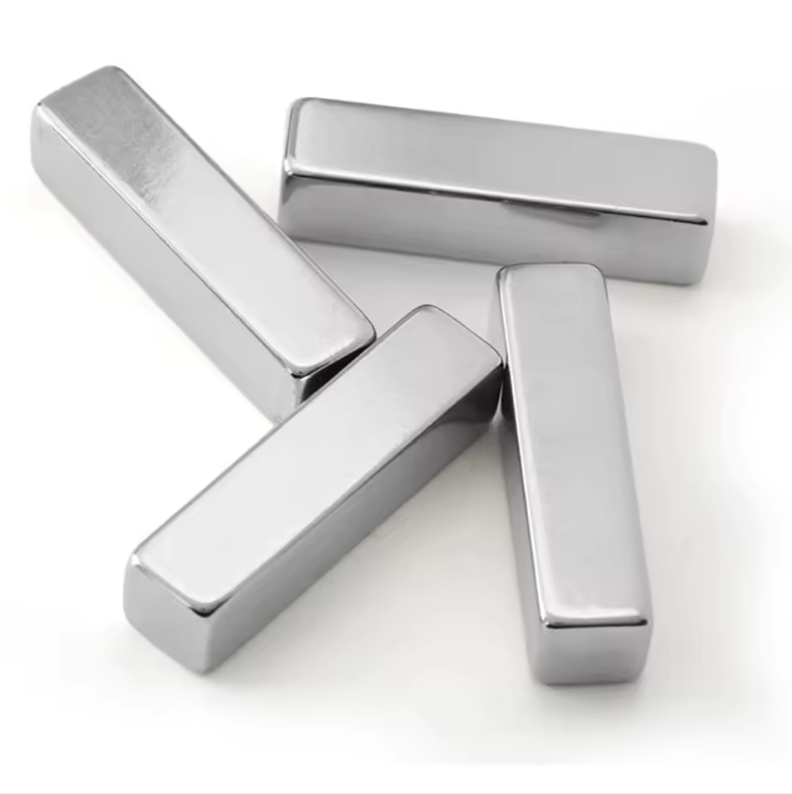
The alignment of magnetic powder prior to sintering is not merely a preparatory step—it is the moment when the material's future anisotropy is actually decided. During the pressing stage, each grain is a tiny independent magnet, and the external field acts like a choreographer, forcing these grains to rotate until their easy axes align. Once the compact is formed, this preferred orientation is locked in place by mechanical interlocking and the binder. Without this early alignment, no amount of heat treatment can recreate the same degree of texture because the grains would simply sinter into a random arrangement.
What makes this stage so critical is the delicate balance between magnetic torque and mechanical friction. The applied field must be strong enough to overcome the interparticle forces, yet the pressing pressure must not crush the grains into misalignment. Engineers often use pulsed fields during compaction, applying short bursts of high intensity that briefly liquefy the rotational freedom of each particle. It is a race against time: align the powders while they still have mobility, before the green compact becomes rigid and unyielding.
In practice, this means the magnet's performance ceiling is set long before the first sintering curve is plotted. A poorly aligned powder batch can never be rescued downstream, no matter how optimized the temperature profile or how pure the alloy. That is why experienced manufacturers treat the alignment press as the heart of the entire production line—because a magnet that does not exist yet is already being told which direction it will prefer to magnetize.
Sintering’s Fine Line Between Dense and Defective
Pushing a compact toward full density during sintering means walking a narrow path where the final few percent of porosity demand disproportionate heat. Thermal energy that closes isolated pores also feeds grain boundaries, letting them sweep across the part and trap gas inside coarsened grains. The result is a component that measures near theoretical density yet fails under modest load because those trapped voids act as stress concentrators.
Operators often nudge peak temperature upward to erase the last visible pores, but this same adjustment can trigger abnormal grain growth or localized melting at particle contacts. In powder systems with broad size distributions, fine particles densify first and shrink away from coarser ones, leaving crack-like separations even when the average density looks acceptable. Holding too long near the melting point of a minor phase can convert a well-distributed liquid that aids rearrangement into pools that leave behind brittle films on cooling.
The practical control lies less in chasing a single density number and more in reading the microstructural signatures of incipient damage. A narrow process window often separates a part with rounded, isolated porosity from one with faceted voids, grain-boundary films, or early-stage swelling. Small shifts in ramp rate, atmosphere, or green density uniformity decide which side of that line the furnace delivers.
Grinding and Coating: Where Microns Decide Performance
Precision grinding rarely gets credit for the final performance of a component, yet the last few microns of material removal set the stage for everything that follows. A bearing race with just half a micron of roundness error will run louder, vibrate more, and wear out far earlier than one ground to a tighter tolerance. The choice of abrasive grit size, bond hardness, and even coolant delivery has to be tuned to remove material in a predictable way at micron scale. Leave a slightly deeper scratch pattern or introduce a faint heat-affected zone, and the part may pass dimensional inspection but fail in service. This is where grinding stops being a bulk operation and becomes a surface engineering step.
Coating performance is equally unforgiving at the micron level. A PVD or CVD layer that varies in thickness by only 0.2 to 0.3 microns can shift the stress distribution on a cutting edge enough to trigger premature chipping or built-up edge. The common assumption that a thicker coating lasts longer often backfires, because beyond a certain point the coating becomes brittle and loses adhesion. What actually matters is controlling the interface: the substrate must be clean and free of micron-scale scratches that act as crack initiation sites, and the coating thickness must match the tool's geometry and cutting conditions. A well-matched coating can double or triple tool life, while a poorly controlled one can make a precision-ground edge perform worse than an uncoated tool.
When grinding and coating are treated as a single process chain, the micron-level interplay becomes even more decisive. A surface that is ground too smooth may not give the coating enough mechanical anchoring, while a surface left too rough leads to early delamination under load. Maintaining a specific Ra window after grinding, and then depositing a coating with thickness tuned to that texture, is often the difference between a tool that withstands thousands of cycles and one that fails in a few hundred. In production, small adjustments to traverse speed or wheel dressing frequency can shift the surface texture enough to change coating adhesion dramatically. Ultimately, the parts that survive in demanding applications are those where the final microns of grinding and the first microns of coating are engineered together, not as separate afterthoughts.
Magnetizing a Rotor in Less Than a Second
The trick to magnetizing a rotor that quickly comes down to a short, violent burst of current. A capacitor bank is charged to a few thousand volts and then dumped through a custom coil wrapped around the rotor. The resulting pulse lasts only a few milliseconds, but the peak magnetic field can exceed 3 teslas—more than enough to snap every magnetic domain in the rotor material into alignment before the pulse fades.
What makes this viable in under a second is the matching between the coil's inductance and the capacitor's discharge curve. The coil geometry, number of turns, and rotor position are tuned so the field reaches saturation exactly when the current peaks. Modern production lines use a spring-loaded or pneumatic fixture to drop the rotor into the coil, trigger the discharge, and eject the part in a continuous cycle—often completing the magnetization step in 300 to 800 milliseconds, including handling time.
The Final Bench Test That Separates Factory Claims from Field Truth
A polished spec sheet can claim anything, but the final bench test doesn't care about brochure numbers. It's where the engine gets heat-soaked for ninety minutes, then asked to deliver rated torque at 45°C intake temps while oil pressure sits at the low end of tolerance. Most units walk back their promise right there.
What separates honest hardware is repeatability. Same load ramp, same coolant temp, same exhaust restriction, three pulls in a row. If the third pull loses more than 2% from the first, that's not a cooling issue—it's a design debt the field will collect with interest. Field truth shows up as hot shutdowns and limp modes the lab never simulated.
FAQ
Most motor magnets are made from neodymium-iron-boron or samarium-cobalt alloys. Neodymium grades offer higher energy density, while samarium-cobalt handles extreme temperatures and corrosive environments better. The factory blends raw elements, melts them under vacuum, and then mills the ingots into fine powder before pressing.
After sintering, the blanks are machined using diamond grinding wheels and wire EDM. Because neodymium magnets are brittle, every pass is controlled for temperature and feed rate. Final inspection uses laser micrometers and CMMs to verify dimensions within a few microns.
Pressing aligns the magnetic domains before sintering. The factory uses either axial or transverse pressing depending on the desired magnetization direction. If alignment is off by even a degree, the finished motor loses efficiency, so operators monitor alignment fields constantly.
Neodymium magnets corrode quickly if uncoated, especially in humid or salty environments. The factory applies multilayer coatings, such as nickel-copper-nickel, epoxy, or Parylene, depending on the motor's operating conditions. Coating thickness is checked with X-ray fluorescence to avoid gaps.
Most magnets leave the factory unmagnetized. They are placed in a magnetizing fixture that applies a brief, intense magnetic pulse, typically 3 to 5 Tesla, to saturate the material. For motor rotors, the fixture is often built to create a specific pole pattern in one shot.
Beyond dimensional checks, the factory runs magnetic moment tests, flux mapping, and crack detection using dye penetrant or ultrasonic scanning. A sample from each lot is also tested for temperature stability and demagnetization resistance under load.
Engineers work from the motor designer's CAD file to build a pressing tool or machining fixture. Prototype lots are usually produced in small batches, then tested for flux and mechanical fit. Once the design is locked, the factory scales up to production volumes.
The material is extremely hard and brittle before coating, so traditional milling or turning is impossible. Almost all shaping happens through powder metallurgy and grinding. Also, every step has to preserve the magnetic properties, which means careful control of heat, pressure, and oxygen levels.
Conclusion
Inside a motor magnet factory, the quiet precision begins long before any finished part appears. Raw blanks are pressed with a uniformity that most people never see, yet this stage dictates everything that follows. Powder alignment happens before the magnet exists as a solid body; magnetic fields are applied to loose particles so that each grain points the same direction. Get this wrong and no later step can fix it. Sintering then walks a fine line between dense and defective. A few degrees too hot or a few minutes too long and the entire batch can crack or lose magnetic potential. Every furnace cycle is a bet against invisible flaws.
Once the blank survives sintering, grinding and coating take over, where microns decide performance. A surface that is slightly off can cause vibration, noise, or even rotor failure under load. Coating must be thin enough not to interfere with magnetic flux but tough enough to resist corrosion for years. Then comes magnetization, a burst of energy that orients the rotor in less than a second. It looks effortless on video, but the coil geometry and pulse timing are tuned to within microseconds. Finally, the bench test separates factory claims from field truth. A rotor that passes every earlier inspection can still fail here, revealing weak spots that only real load conditions expose. That final checkpoint is where precision manufacturing proves itself or falls apart.
Contact Us
Contact Person: Kelvin Lo
Email: [email protected]
Tel/WhatsApp: 0769-88561131
Website: https://dawamagnetic.com/