

Current Sense Resistor Top Picks for Precision Power Measurement
2026-11-18
Precision power measurement often hinges on a component that rarely gets the spotlight: the current sense resistor. A fractional milliohm drift here or a subtle thermal swing there can quietly distort readings in battery gauges, motor controls, and power converters. Instead of treating these parts as an afterthought, it pays to look closely at how construction, alloy choice, and layout affect the numbers you trust. At Milliohm, we have been sorting through low-ohmic options to find the ones that hold their accuracy when it matters most. Here are the top picks worth considering for your next precision design.
Where Metal Foil and Thin Film Earn Their Place on the Shortlist
When a design team narrows materials for tight-tolerance current sensing, the conversation tends to swing between bulk alloys and plated copper—until thermal drift and board real estate push both options into awkward corners. Metal foil earns its spot here because the resistance element can be patterned directly into a thin, stress-relieved alloy sheet, keeping the temperature coefficient flat without adding a separate shunt. Thin film arrives on the same shortlist for low-noise analog front ends, where a few hundred nanometers of nichrome or tantalum nitride deliver stable sheet resistance and predictable laser trimming.
Flexible circuits and wearable monitors are another place the two earn their keep. Rolled or electrodeposited foil gives stretchable interconnects enough current-carrying capacity to survive repeated bending, while thin film coatings on polymer substrates hold impedance steady across hundreds of thousands of flex cycles. Rather than competing head-to-head, they often split the bill: foil carries the power, thin film handles the sensing traces and contact pads.
There is also a quieter bench in specialty packaging and precision optics. Metal foil tapes and laminates show up in thermal straps and EMI shields where low mass and conformability matter more than raw strength. Thin film stacks, meanwhile, earn a place on the shortlist for mirrors, filters, and transparent heaters because they can be deposited with tight optical density and sheet resistance. In those selection meetings, the deciding factor is rarely a single property—it is the way the material survives lamination, soldering, or years of thermal cycling without drifting.
The Case for Low TCR in Long-Run Power Monitoring
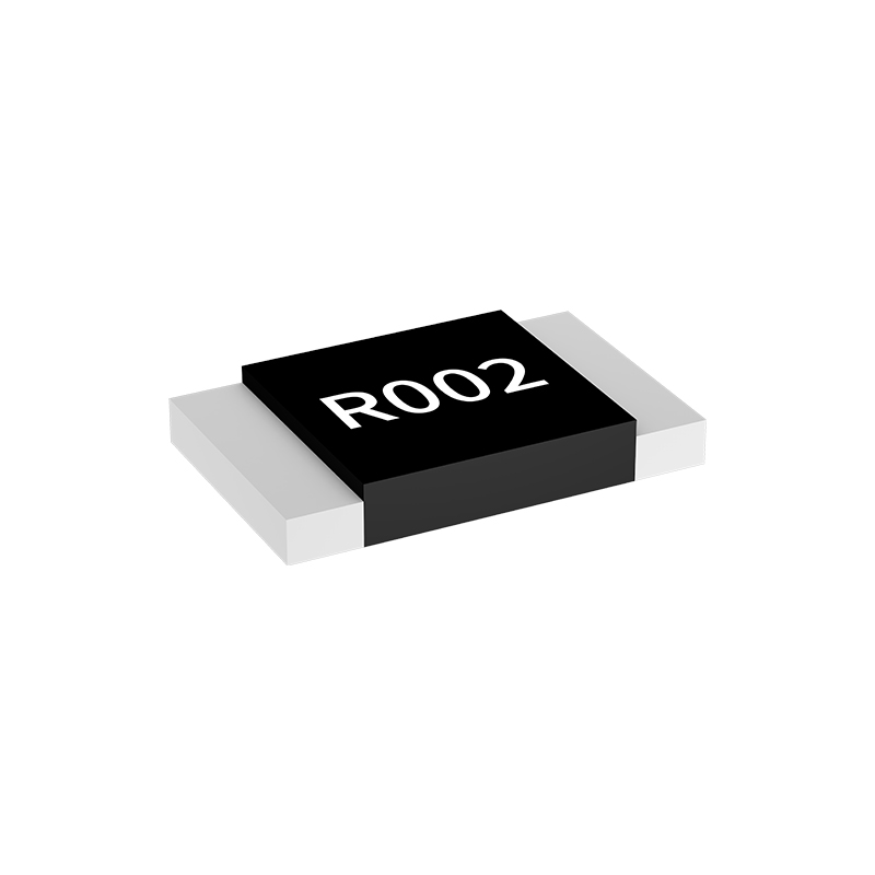
In long-run power monitoring, the sense resistor is often the quiet anchor of the measurement chain, but its temperature coefficient quietly reshapes every reading that passes through it. A high TCR part may look acceptable on a bench at stable room temperature, yet months of thermal cycling and seasonal shifts introduce small resistance changes that accumulate into drift far larger than the initial tolerance suggests. Choosing a low TCR alloy keeps that anchor from wandering, so the conversion from millivolts to amps remains trustworthy without aggressive temperature compensation.
Self-heating adds another layer that only becomes visible over extended operation. When load current flows continuously, the resistor warms, its value shifts, and the reported power starts to reflect the temperature rise rather than the actual load change. Low TCR materials reduce this coupling between measurement and dissipation, which matters most in energy audits, battery coulomb counting, and industrial telemetry where the error persists for weeks rather than seconds. The benefit is not a dramatic improvement on a single sample; it is the absence of slow, systematic divergence across the full service interval.
There is also a practical cost argument hiding inside the specification. Compensation circuits and frequent recalibration can mask some drift, but they add complexity, downtime, and recurring labor. A low TCR element often allows the design to run with simpler analog front ends and longer calibration windows, shifting the burden from maintenance schedules back to the component itself. Over a multi-year monitoring deployment, that change in temperature stability becomes one of the few design decisions with a payback that extends long after the initial BOM review is forgotten.
Kelvin Connections and the Milliohm Resistors That Reward Them
Measuring resistance below a single ohm is less about the meter and more about the path the current takes. A standard two-wire reading folds the test leads into the result, and at milliohm levels that tiny contact resistance can dwarf the part you are trying to characterize. Kelvin connections sidestep this by forcing a known current through one pair of leads while a separate pair senses voltage directly at the component terminals. The sense leads carry almost no current, so their resistance drops out of the equation, leaving only the voltage developed across the device itself.
The reward appears when those four terminals meet a well-designed board. Current-sense resistors with dedicated Kelvin pads will always outperform a generic two-pad part in a battery gauge or motor drive, because the measurement becomes immune to solder joint variability and copper trace heating. That immunity translates into stable offset voltages, repeatable current limits, and fewer firmware corrections that try to hide a noisy sense signal. If the sense lines join the high-current path at a single via or shared pad, you have not made a Kelvin connection; you have only made a more complicated two-wire measurement.
Thermal EMF Tests That Separate Good Enough From Great
A thermal EMF test sounds simple until you watch the numbers move for the first twenty minutes. The gap between acceptable and exceptional usually comes down to whether the setup is allowed to settle before data is taken. Stable ambient conditions, clean copper-to-copper junctions, and enough time for the entire measurement loop to reach thermal equilibrium matter more than the resolution of the nanovoltmeter. Rushing this step produces values that look repeatable but mostly describe the room, not the device.
The next dividing line is how the data is challenged. Reversing current, swapping lead polarity, repeating the soak after a disturbance, and checking zero drift across several hours expose small instabilities that a single pass would miss. A part that only meets a threshold on the first attempt is not the same as one that stays within a narrow band through all of it. Suppliers that show that kind of stability are typically the ones whose contacts and materials behave at microvolt levels in the field.
Balancing Sense Voltage Drop and Measurement Resolution
The choice of shunt resistance turns into a practical tug-of-war between the voltage dropped across the sense element and the resolution available at the measurement front end. A larger resistance produces a stronger sense voltage for a given current, which lifts the signal further away from amplifier offset and noise. That improves the ability to resolve small changes in load current, but it also inserts more series loss, heats the resistor, and can disturb the very rail being monitored.
In low-current or battery-powered designs, the acceptable drop is often only a few tens of millivolts at full load, yet the system may still need to capture milliamp-level variations. Here the balance leans on gain staging, reference choice, and the noise floor of the analog-to-digital converter rather than on increasing the shunt value. Designers often work backward from the minimum current step that must be detected, then check whether the resulting full-scale sense voltage remains acceptable under worst-case load and thermal conditions.
There is no single ideal drop that fits every board. A compact supply with tight efficiency targets may tolerate 20 mV or less, while a motor-drive stage with higher headroom might allow 100 mV or more if it keeps the current loop stable and the measurement repeatable. The better approach is to treat the sense voltage as a budget: spend just enough of it to keep low-end resolution credible without giving away too much efficiency or thermal margin.
A Quick Validation Routine for Precision Power Readings
Precision power readings only matter if you can trust the numbers on the screen. A quick validation routine doesn't need a lab full of gear—just a known load, a stable source, and about ten minutes of focused attention. Start by letting the meter warm up for at least five minutes so internal references settle. Then connect a resistive load with a documented tolerance, something like a 50-ohm terminator or a fixed-value power resistor, and compare the displayed watts against your own calculation from voltage and current. Discrepancies beyond two or three percent usually point to calibration drift, a loose connector, or an incorrect impedance setting.
The second step is to check repeatability under the same conditions. Take three readings thirty seconds apart and note the spread. A meter that jumps by half a watt on a stable load is telling you more about its own noise floor than about the actual power. If you have access to a second instrument, even a mid-range one, run the same test side by side. You're not looking for perfect agreement—you're looking for whether the offset stays consistent. Consistent offsets can be compensated for; random swings cannot.
Finally, document what you observe without turning it into a formal ceremony. A handwritten note with the date, load value, ambient temperature, and the three readings is enough. Over weeks, those notes reveal drift patterns that a single spot-check never will. The goal isn't to prove the meter is perfect—it's to know exactly how imperfect it is, and whether that imperfection still fits your measurement needs.
FAQ
It comes down to tight resistance tolerance, a low temperature coefficient, and stable behavior under load. A four-terminal Kelvin layout also helps by keeping lead and trace resistance out of the measured value.
Resistance tolerance, TCR, power rating, thermal EMF, and parasitic inductance. For sub-milliohm values, the current path geometry and pad layout often influence accuracy as much as the nominal resistance does.
Metal alloy parts usually tolerate higher pulse power and have low thermal EMF, while metal foil offers extremely tight tolerance and low TCR. For DC precision, foil tends to be better; for rugged high-current sensing, alloy is often the safer pick.
They separate the current-carrying electrodes from the voltage-sensing electrodes. That removes PCB trace resistance and solder joint variation from the measurement, which becomes critical below roughly ten milliohms.
For bench-grade accuracy, four-terminal metal foil resistors in the one to ten milliohm range are strong candidates. For compact power monitoring, low-TCR metal alloy chip resistors in 2512 or 3920 footprints with one percent or better tolerance work well.
Ideally below plus or minus fifty ppm per degree C, and below plus or minus fifteen ppm per degree C in high-accuracy designs. Since self-heating can push the resistor temperature well above ambient, a low TCR directly reduces full-load measurement error.
The usual compromises involve tolerance, TCR, and package size. A precision four-terminal part may cost several times more than a standard thick film chip, but it reduces calibration effort and long-term drift in the field.
Conclusion
Selecting a current sense resistor for precision power measurement rarely comes down to a single datasheet number. Metal foil and thin film parts tend to earn their place because their resistive element remains stable under pulse loads and repeated thermal cycling, while thick film alternatives often drift when the same circuit is pushed hard. For continuous monitoring over weeks or months, a low temperature coefficient of resistance matters more than initial tolerance, since even a few ppm per degree Celsius shift can accumulate into measurable error as ambient temperature moves through a normal operating day. At milliohm values, the physical layout becomes part of the measurement. Kelvin connections separate the current path from the sense path, so lead and trace resistance no longer masquerade as a larger voltage drop across the element. Thermal EMF testing adds another filter because junctions between dissimilar metals can generate microvolt level offsets that look like small load changes, and well made resistors keep this effect predictably low.
The real balancing act sits between sense voltage drop and resolution. A larger resistance improves signal to noise against the ADC noise floor, but it also steals power from the rail and heats up under high current. A smaller value preserves efficiency yet demands a low offset, high gain front end to recover a clean reading. In practice, a quick validation routine helps separate a properly selected part from a marginal one. Push a known current through the resistor, wait for thermal settling, and verify that the measured drop matches the expected value while watching for drift caused by self heating or poor soldering. When the resistor combines low TCR, low thermal EMF, and a sensible milliohm value, precision power numbers stop being a matter of luck and become repeatable.
Contact Us
Contact Person: Yuying Gao
Email: [email protected]
Tel/WhatsApp: +86 18926013721
Website: https://en.milliohm.net/